INDEX
1. What is the inverter?
Inverters should not be confused with other softstart devices, which have similar appearances but different operating concepts, characteristics and performances.
The softstart is an electronic starter that allows the engine to be started and stopped gradually by acting on the voltage and current parameters, but once the start-up is complete, it powers the engine at a fixed frequency of 50 Hz, or is even bypassed.
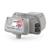
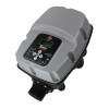
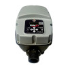
The inverter instead manages the variation of the motor speed by varying the power frequency. The ability to vary the frequency is not only limited to the start and stop phases but also during the entire running time of the motor. They are specifically designed for the electronic control and management of pumping systems with the aim of ensuring low operating costs, constant pressure and silent operation. The achievement of these objectives is made possible by the reduction of the starting currents, by the lower absorption of the electric pumps in operation and by the gradual shutdown of the motors whose rotation is modulated according to the quantity of liquid taken from the system. This eliminates the waste of energy typical of pumping groups operated by pressure switches or other electronic equipment.
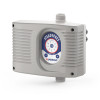
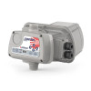
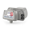
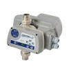
The smoothness with which the pumps start and stop also contributes to the substantial reduction of water hammer, benefiting the comfort and longevity of the system. The inverters can manage surface pumps, submersible pumps, heating and cooling pumps regardless of their flow rate and operating pressure; in addition to the electrical connection, they only require a sensor that reads the water pressure of the system. They can be installed either on the motor, replacing the cover used to close the terminal board, or on the wall and are presented in horizontal or vertical versions; they easily replace the magnetothermal protection panels of the electric pumps, protecting them from failures caused by overvoltages, abnormal current absorption, dry running or with closed delivery.
They stand out for reliability and ease of installation because they are self-installing devices that automatically detect the pump curve and all the parameters necessary for calibration, reading the electrical quantities of the motor from the power cable only and then, based on these and the data received from the pressure sensor, vary frequency and voltage, automatically regulating the delivery pressure. Both the maximum working pressure of the pump and the minimum stop flow for closed delivery and dry operation are self-regulated with excellent precision.
2. The three main reasons for choosing to use an inverter
Inverter technology has been revolutionizing the world of plumbing for a few years now. However, many people wonder if it is just a marketing gimmick.
Let's see below three reasons why it can be very useful.
2.1 Constant pressure
The inverter can vary the voltage and frequency of the output alternating current, thus allowing the motor revolutions to be modulated according to the water demand and therefore always guaranteeing a constant pressure regime in the system. So no more sudden changes when opening the taps, or annoying pressure shortages when you require enough water. Once you have chosen the desired pressure, the inverter will give you constant pressure, always.
2.2 Energy saving
If the engine revolutions are modulated according to the actual request, the inverter will operate the system not always at its maximum capacity but always based on the requested load. This guarantees not only energy savings but also durability, obtaining less wear of the system. Some models combine all these functions with the comfort of greater silence and an important parameter such as soft start, to guarantee adequate starting in case of system start-up.
2.3 Total protection
Linked to inverter technology is the ability to better and more precisely control any changes in operating regimes. This is then combined with a series of additional protections such as dry running control of the pump, overpressure protection, supercharging, anti-lock function and restart control.
3. When is the inverter used in pumping systems?
The applications of the inverter in pumping systems become multiple, even more so when the logic of its operation is understood. For example, in addition to allowing me to maintain constant pressure, an inverter can allow me to maintain constant flow or water level.
It is important to clearly define what you want to achieve, as the inverter is often used improperly (only to achieve gradual starts and stops) or incorrectly, making its use and investment useless. It makes little sense to use the inverter to obtain flow or pressure adjustments on more than 2 units operating in parallel, as the adjustment could be subject to oscillations, furthermore the use of 3 or 4 machines in parallel, operating at fixed speed, already allow a good fractionation of the total pumping capacity. In the pumping of waste water, inverter management, as an alternative to the on-off system, can be used to reduce energy losses; this is in cases where the hydraulic system has high load losses due to friction, compared to the geodetic difference in height (pumping under pressure on long pipes)
3.1 Using the inverter to maintain constant pressure
Our pumping system takes water from a storage tank and pumps it into a distribution network. The aim is to maintain a certain pressure in the network, despite the fact that the flow rates requested by users vary greatly from time to time.
Solution:
By adopting an inverter and managing the pumping with the “constant pressure” logic, we can solve the problem. By detecting the pressure on the collector, with a pressure sensor it will be possible to regulate the speed of the pumps and consequently the pressure in such a way that a set-point set by the operator is maintained. In these cases, an absolute constant pressure is not required, but rather an operation within a certain range.
Example of constant pressure pumping:
Operating logic. The operator defines a pressure set-point. The system is activated upon operator consent, the speed regulation is carried out according to a PID algorithm that depends on the deviation of the measured pressure from the set-point. If the pressure increases, the pump will be operated at a lower speed, if the pressure drops, the pump will increase in speed. In this way, a nearly constant network pressure will be obtained, and in any case within the set tolerance bands.
Equipment required: 1 analog pressure sensor. 1 pump inverter.
3.2 Using the inverter to maintain the constant level
We have a sewer well or a wastewater storage tank. The inflows of liquids vary greatly from moment to moment, so we find large variations between the maximum and minimum incoming flow rates. The pump is stressed by the numerous starts and stops.
Solution:
By adopting an inverter and managing the pumping with the “constant level” logic, we can solve the problem. By detecting the level in the tank with an analog meter, it will be possible to adjust the speed of the pump and consequently the flow rate so that the level remains constant, that is, the more water enters the tank, the more is pumped out of the system.
Example of constant level pumping:
Operating logic. The operator defines a level set-point such as to obtain the maximum filling capacity of the well; the system is activated when the enabling threshold is reached, the speed regulation is carried out according to a PID algorithm that depends on the deviation of the level in the tank from the set-point. If the level increases, the pump will be operated at a higher speed, if the level decreases, the pump will slow down. In this way, the number of pump start and stop sequences will be limited to a minimum.
Equipment required: 1 analog level sensor. 2 digital level switches. 1 pump inverter. 1 management controller.
4. Use of the inverter to maintain constant flow rate
We are making an initial pumping of a purifier. Our aim is to feed the treatment line with a constant flow in order to obtain maximum efficiency from the plant.
Solution:
By adopting an inverter and managing the pumping with the “constant flow” logic, we can solve the problem. By detecting the flow rate on the collector, with a flow meter it will be possible to regulate the speed of the pump and consequently the flow rate in such a way that a set-point set by the operator is maintained. It is obvious that this system requires a buffer tank to compensate for peak and low flow times.
Example of constant flow pumping:
Operating logic. The operator defines a flow rate set-point. The system is activated when the enabling threshold is reached, the speed regulation is carried out according to a PID algorithm that depends on the deviation of the measured flow rate from the set set-point. If the flow rate increases, the pump will be operated at a lower speed, if the flow rate decreases, the pump will increase speed. In this way, a pumped flow with an almost constant flow rate will be obtained. It is important to have an adequate buffer volume.
Equipment required: 1 analog level sensor. 1 flow meter. 2 digital level switches. 1 pump inverter. 1 management controller.


